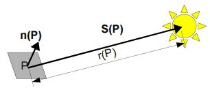
Light striking an object at a certain direction would get reflected a specific orientation. Detecting this reflected light would only mean capturing one component of the intensity. This means that illuminating an object in different positions results to different shadings in the images of the object. Photometric stereo is a technique of using these different shading information for 3D reconstruction.
In this activity, it is assumed that the light striking the object are uniform plane waves. From the figure above, the direction S(P) is now a constant for all points P on the object. This allows a simple calculation of this direction, which is just proportional to the location of the light source with respect to the object:

(each row represents the 3D coordinates of one light source with the object as origin)

(k is the proportionality constant)
Intuitively, the brightness of a point P on the object would be given by the equation
where ρ(P) represents the reflectivity of that point, ň(P) is the normal vector at point P and S0 is the vector from the point to the source, which is now considered a constant for all points on the object due to the plane wave illumination. The intensity detected is proportional to this brightness by the same proportionality constant k in the equation for V:
We can set:so that from a set of images of the object using N different light source locations:
we can calculate by matrix operations:

Upon knowing g, the surface normal vectors of the object can be calculated:

Upon knowing g, the surface normal vectors of the object can be calculated:
In this activity, four images are obtained using four different light sources, as shown below, with the corresponding light source locations. (Note: The images shown below are normalized individually).
Image 1 (V1 = {0.085832, 0.17365, 0.98106})
Image 2 (V2 = {0.085832, -0.17365, 0.98106})
Image 3 (V3 = {0.17365, 0, 0.98481})
Image 4 (V4 = {0.16318, -0.34202, 0.92542})
Applying photometric stereo described above, the shape of the object was reconstructed and the result is shown below. The surface of the reconstruction is not very smooth. However, the shape is still defined.


No comments:
Post a Comment